Optimizing the design of data center utilities
January 07, 2025
January 07, 2025
How the Neher-McGrath Equation can inform underground installation
We know information is power.
But what about the power needed to store, protect, and distribute that information?
By 2025, some predict global data storage will exceed 200 zettabytes (200 million terabytes). Half of that will be in “The Cloud.” While data cloud storage conjures images of bits and bytes floating around above us, the reality is much more grounded. Data centers are the backbone of an ever-growing infrastructure supporting information storage and distribution.

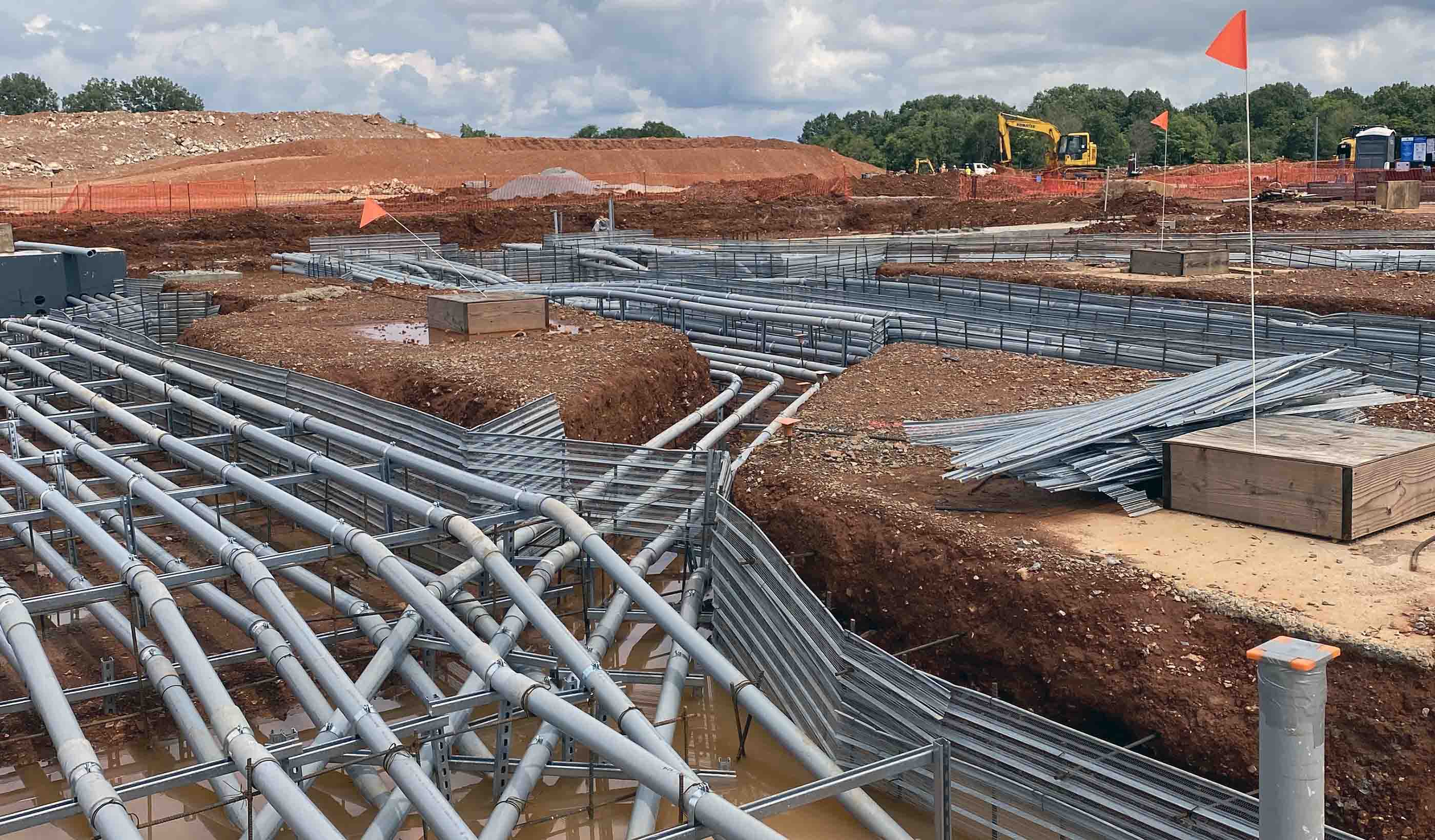
Materials surrounding an underground utility can affect heat transfer.
We need to design these mission-critical facilities to be safe, secure, and efficient. Often, that comes down to their electrical utilities. In other words, the power of information comes down to how you power that information.
Electrical duct banks provide a protected pathway for buried electrical cables and are used to distribute power to a data center. They often use extremely large feeders. Unlike commercial applications that carry around 50 percent of their design load, these feeders often carry from 95 to 100 percent of the design load. This leads to considerable heat contribution. It also directly affects how deep we can bury duct banks and what materials we can use to build them. This scenario is truly site-specific and can have a significant impact on the cost of the project. It is crucial to have accurate heat calculations to determine the proper cable system needed to power these facilities.
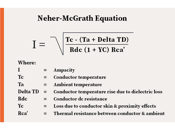
Enter the Neher-McGrath formula.
John Hutchins Neher and Martin Hager McGrath published a paper in 1957 on how to calculate the maximum current a cable can handle. This is called ampacity, which we’ll discuss later. The basis of their work was the understanding that the movement of heat through a cable system’s thermal resistances will cause a temperature rise. This measurement could be predicted at various points in the cable system. The standards, guidelines, and regulations from these two electrical engineers are still used today.

Created in 1957, the Neher-McGrath Equation still proves useful today.
In its simplest form, the Neher-McGrath Equation appears straightforward. But for electrical engineers, its application can be much more complicated and nuanced.
Perhaps formulas or equations aren’t the best way to describe this method for estimating the steady-state temperature of electrical utilities and power cables. These words suggest that we can solve problems with simple data inputs and brute-force calculations. The Neher-McGrath approach, however, serves as more of a guide to account for a wide range of environmental impacts. That makes each calculation case specific. Figuring out the proper data inputs requires the experience and imagination of a skilled electrical engineer.
Ampacity is the largest electrical current that a wire or cable can carry without overheating. Certain variables can change a wire’s ampacity. For example, a wire with a higher temperature rating has a higher ampacity. So does a thicker wire.
But if the temperature around the wire goes up, the ampacity goes down. Putting the wire underground has the same effect.
Large project sites, like data centers, typically route utilities underground. This makes the Neher-McGrath equation critical. The heat calculations determine the temperature rise resulting from the reduced heat transfer of the underground installation. Some factors that affect heat transfer include:
Remember, a rise in temperature means reduced ampacity for the cable. That could require larger feeder sizes or multiple sets to safely carry the same as an overhead cable. As previously noted, data centers typically run at 95 to 100 percent load factor compared with 50 percent for most commercial facilities. This leads to much more heat on data center feeders.
Why does this matter? Because a larger feeder size and quantity can greatly impact the cost of a data center project. For example, here are three things can impact a project’s schedule and overall cost:
It is crucial to have accurate heat calculations to determine the proper cable system needed to power these facilities.
When installing duct banks, options exist to limit the impacts of the heat produced by the feeders. One choice is to install the feeders as shallow as possible, allowing the heat to dissipate more quickly from the earth. Frost depth requirements may limit this approach. Duct banks must be installed below the region’s frost line or they risk heaving.
Installations also require coordination with the routing of the other underground utilities on the site. And entry points into the buildings must factor in the structural elements of the project. Designs must route feeders below structural foundations and outside of their “zone of influence” (or no-fly zones for utilities) because they could end up crushed by structural forces.
Surrounding materials and the associated thermal resistivity is also a key factor. The lower the thermal resistance, the better the heat transfer capability. This material is often made up of native soil with distinct properties. For example, sandy, rocky, and clay soils display different thermal characteristics. The water content and ambient temperature of the native soil also affects thermal characteristics.
Using a concrete encasement can also help control the effects of heat on cable systems. But even here regional differences can have an impact. Concrete generally has a good thermal resistivity, or rho value, of 55-75 degrees C-cm/W (Celsius-centimeter per watt). However, concrete rho values tend to vary by region. This is because the aggregate is usually sourced locally. The contractor will need to test concrete to confirm thermal resistivity values.

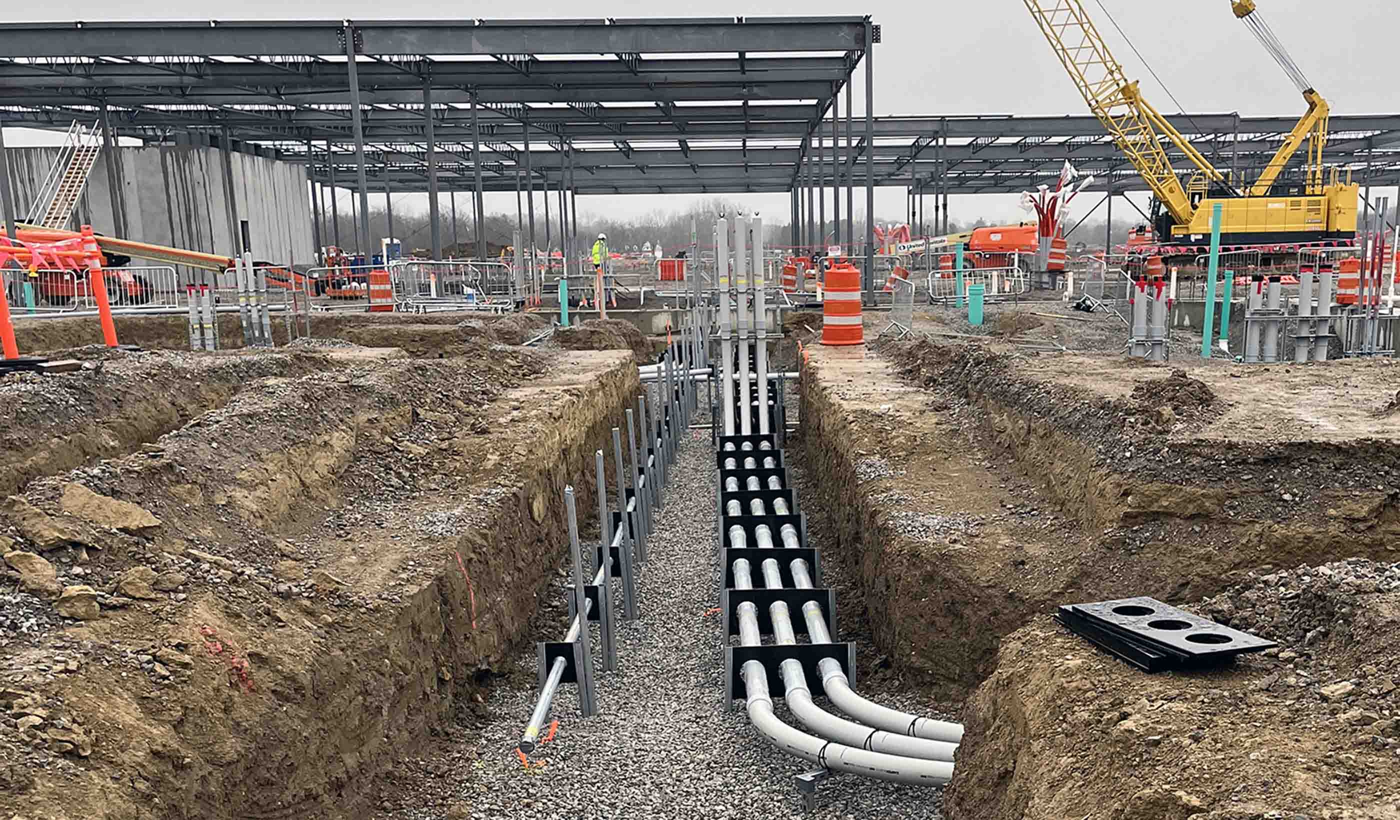
Heat transfer can be impacted by the depth of the buried cables.
If concrete slabs are installed above a duct bank, the electrical design should account for the depth and extent of the slab. Designers should also understand the gravel component below and how deep that gravel layer is. Gravel is often used as a layer below slabs to prevent cracking and as an alternative backfill material to native soil.
Thermal resistivity is highly dependent on the size of the gravel. The larger the gravel, the larger the air pockets within the gravel that can trap heat. For example:
Neher and McGrath’s impact on the electrical engineering industry can’t be overstated. But it’s important to remember the formula they offered nearly seven decades ago is only as good as the engineer inputting the variables.
It’s essential to have a thorough understanding of the factors affecting heat transfer and thermal resistivity. Without that, it’s nearly impossible to find the best solution for supplying power to today’s data center utilities. Knowledge is indeed power.
A version of this blog was published in Building Design + Construction.